
Understanding the ASPRS Positional Accuracy Standards: Evolution, Impact, and What’s New
![]() Author: Tim Burrows, Account Manager, AeroTech Mapping
Author: Tim Burrows, Account Manager, AeroTech Mapping
In the aerial mapping, surveying, and engineering professions, positional accuracy isn’t a minor detail; it’s everything. A few tenths of error can throw off the placement of utilities, derail planning, or create safety risks. Improvements in Geospatial mapping technologies (such as cutting-edge digital cameras and LiDAR) enable faster delivery of highly accurate and precise data. While the tools evolve rapidly, the adoption of new standards is slower. Many agencies still reflect outdated assumptions built for legacy workflows. As a result, agencies continue to rely on benchmarks that no longer match the performance of modern technology. The gap between what is possible, what is required, and what professionals need is growing wider. To bridge that gap, updated accuracy standards built around today’s capabilities and technologies need to be adopted. That means tighter tolerances, adaptive validation methods, and alignment with continuously advancing positioning systems. Fortunately for the industry, the American Society of Photogrammetry and Remote Sensing (ASPRS) has dedicated professionals committed to testing and proving out the latest technology and workflows to establish these standards.
What is ASPRS and Why Does It Matter?
About ASPRS
ASPRS was founded in 1934 as the American Society of![]() Photogrammetry (ASP) with the original mission of keeping Geospatial professionals informed about photogrammetry and creating a space for discussion and networking. The 12 founding members, led by Col. Claude Birdseye, met in Washington, D.C., to form the organization and represented agencies and firms including the U.S. Corps of Engineers, Forest Service, Coast and Geodetic Survey, Geological Survey, Soil Erosion Service, Fairchild Aerial Survey (through acquisitions, now part of Northrop Grumman), and W.N. Brown, Inc. The name was changed to the American Society of Photogrammetry and Remote Sensing (ASPRS) in 1985 as it became clear that the industry was expanding beyond just photogrammetry and into remote sensing technologies. ASPRS has become the leading professional organization focused on advancing the science and application of photogrammetry, remote sensing, and geospatial technologies. Its members include surveyors, engineers, mapping professionals, academics, and government agencies. The organization’s mission is to promote effective use of remote sensing and geospatial data through education, innovation, and developing standards.
Photogrammetry (ASP) with the original mission of keeping Geospatial professionals informed about photogrammetry and creating a space for discussion and networking. The 12 founding members, led by Col. Claude Birdseye, met in Washington, D.C., to form the organization and represented agencies and firms including the U.S. Corps of Engineers, Forest Service, Coast and Geodetic Survey, Geological Survey, Soil Erosion Service, Fairchild Aerial Survey (through acquisitions, now part of Northrop Grumman), and W.N. Brown, Inc. The name was changed to the American Society of Photogrammetry and Remote Sensing (ASPRS) in 1985 as it became clear that the industry was expanding beyond just photogrammetry and into remote sensing technologies. ASPRS has become the leading professional organization focused on advancing the science and application of photogrammetry, remote sensing, and geospatial technologies. Its members include surveyors, engineers, mapping professionals, academics, and government agencies. The organization’s mission is to promote effective use of remote sensing and geospatial data through education, innovation, and developing standards.
Why the ASPRS Standards Exist
ASPRS develops national accuracy standards for digital geospatial data. These standards exist to:
- Promote best practices in data collection, processing, and reporting.
- Standardize how accuracy is defined and measured, so deliverables are consistent and comparable across projects, vendors, and platforms.
ASPRS standards aren’t just guidelines; they’re widely adopted benchmarks that shape how the industry works:
- Mapping firms use ASPRS standards to validate deliverables before handing them off to clients.
- Surveyors integrate them into their QA/QC processes to ensure that airborne and terrestrial data align with ground truth.
- Civil engineers depend on these standards to guarantee the accuracy of inputs used in modeling, design, and construction.
In short, ASPRS standards help ensure that the data feeding into real-world projects is reliable, defensible, and aligned with the capabilities of modern technology.
Evolution of the ASPRS Standards
For over three decades, ASPRS has been a guiding force in defining positional accuracy standards. As technology has advanced, so have the benchmarks for what constitutes accurate spatial data.
Here’s a look at how the ASPRS Accuracy Standards have evolved to keep pace with innovation:
1990: The Era of Large-Scale Map Standards
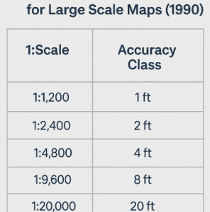
Before the rise of digital mapping, positional accuracy was tightly bound to physical map scales and contour intervals. The 1990 ASPRS standards focused on the paper map era’s requirements, with accuracy thresholds tied directly to how a map was intended to be used in the field. These standards were practical for their time but lacked the flexibility to address the complexities of emerging digital datasets.
2014: Edition 1, Version 1 – Embracing the Digital Age
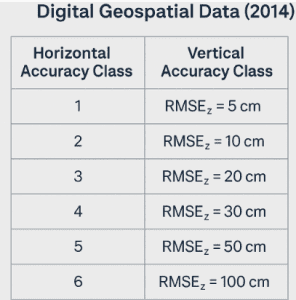 By 2014, the geospatial community had fully transitioned into a digital environment. The first edition of the ASPRS Positional Accuracy Standards for Digital Geospatial Data introduced a major paradigm shift: accuracy was now assessed using Root Mean Square Error (RMSE) and robust statistical methods. RMSE measures how closely the data matches the expected error by finding the square root of the average of the squared differences between the expected and actual values. The previous method was a 95% confidence level, which describes the probability that a position’s error will be within a specific tolerance. This update represented a move away from map-scale-based assessments and toward measurable, repeatable evaluations of digital data accuracy.
2023: Edition 2, Version 1 – A Modular, Best Practices Approach
In 2023, ASPRS released a significantly updated Edition 2, marking a modernization in both framework and content. The new modular format allowed greater flexibility across a variety of sensor platforms and project types. Notable updates included:
- Dropped the 95% confidence level in favor of more flexible statistical reporting.
- Relaxed control point requirements, making standards more attainable without sacrificing quality.
- Previously required GCPs to be 4x better than the target accuracy of the final product and check shots to be 3x. This was reduced to 2x.
- This is due to advancements in sensor and processing technology, such as cutting-edge digital cameras, GNSS systems, and the processing software that produced more accurate products than traditional photogrammetric workflows.
- Mandated reporting of checkpoint accuracy, ensuring transparency in data validation.
- Eliminated rigid VVA (Vegetated Vertical Accuracy) pass/fail criteria, replacing it with a focus on NVA (Non-Vegetated Vertical Accuracy).
- This was done as VVA results are significantly impacted by factors outside of the LiDAR sensor’s performance (difficulty reaching ground through dense canopy or limitations of the accuracy of checkpoints in those areas), and using it as a pass/fail criteria to accept/reject a project could lead to falsely rejecting projects where the LiDAR sensor performed to specifications.
- Set minimum checkpoint counts (30) and capped large project checks (120), balancing rigor with practicality.
- Introduced 3D positional accuracy, reflecting growing demand for accurate elevation data.
- Launched Best Practices Addenda, providing actionable guidance for real-world implementation.
2024: Edition 2, Version 2 – Refinement and Future-Readiness
The latest update in 2024 further clarified and strengthened the standards:
- Reinforced RMSE as the single accepted measure for horizontal and vertical accuracy, promoting consistency across projects.
- Expanded to support emerging technologies, including unmanned aerial systems (UAS), LiDAR, and oblique imagery.
- Added detailed definitions such as “data internal precision,” helping practitioners distinguish between absolute accuracy and internal consistency.
- Refined rules for control points and statistical tests, ensuring data quality while adapting to modern workflows.
Most Impactful Standards for Aerial Mapping, Surveyors, and Engineers
The 2024 update to the ASPRS Positional Accuracy Standards marks a significant step forward in aligning geospatial practices with modern digital workflows. These refinements are particularly impactful in aerial mapping, surveying, and civil engineering. These are the key changes and why they matter.
RMSE-Only Accuracy Reporting
One of the most notable changes is the shift to Root Mean Square Error (RMSE) as the sole metric for accuracy reporting. By eliminating the traditional 95% confidence level, ASPRS simplified the interpretation and comparison of results. RMSE is more intuitive, easier to compute, and better aligned with industry-standard statistical methods, reducing confusion across disciplines.
| Accuracy Class | RMSE Horizontal (CM) |
RMSE NVA (cm) |
RMSE VVA (cm) |
RMSE3D (cm) |
Seamline Mismatch (cm) |
Swath-to-Swath Vertical (cm) |
Within-Swath Vertical (cm) |
|---|---|---|---|---|---|---|---|
| 1 cm | 1.0 | 1.25 | 2.0 | 1.8 | 2.0 | 1.5 | 1.0 |
| 2 cm | 2.0 | 2.5 | 4.0 | 3.6 | 4.0 | 3.0 | 2.0 |
| 5 cm | 5.0 | 6.3 | 10.0 | 9.0 | 10.0 | 7.5 | 5.0 |
| 10 cm | 10.0 | 12.5 | 20.0 | 18.0 | 20.0 | 15.0 | 10.0 |
| 20 cm | 20.0 | 25.0 | 40.0 | 36.0 | 40.0 | 30.0 | 20.0 |
| 50 cm | 20.0 | 62.5 | 100.0 | 90.0 | 100.0 | 75.0 | 50.0 |
Horizontal, Vertical, and 3D Accuracy Classes
The standards now provide distinct accuracy classes for horizontal (XY), vertical (Z), and 3D positional accuracy, recognizing that modern mapping products often require integrated spatial dependability. The addition of a true 3D accuracy class is especially relevant for applications such as design scale engineering projects, where a single metric must account for all spatial dimensions.
Vertical Accuracy of the ASPRS Positional Accuracy Standards for Digital Geospatial Data, Edition 2, Version 2 (2024) Compared to Legacy Standards
| Vertical Accuracy Class |
NVA RMSEV (cm) |
Equivalent Class 1 Contour Interval per ASPRS 1990 (cm) |
Equivalent Class 2 Contour Interval per ASPRS 1990 (cm) |
Equivalent Contour Interval per NMAS (cm) |
|---|---|---|---|---|
| 1 cm | 1.0 | 3.0 | 1.5 | 3.29 |
| 2.5 cm | 2.5 | 7.5 | 3.8 | 8.22 |
| 5 cm | 5.0 | 15.0 | 7.5 | 16.45 |
| 10 cm | 10.0 | 30.0 | 15.0 | 32.9 |
| 15 cm | 15.0 | 45.0 | 22.5 | 49.35 |
Survey Ground Control & Checkpoint Requirements
ASPRS also modernized requirements for survey ground control and independent checkpoints:
- Relaxed accuracy thresholds offer more realistic expectations for field conditions, particularly in remote or complex terrain (enabling the use of GNSS to set control points), and considers advancements in sensor and processing technology.
- The error from checkpoints is now factored into final accuracy assessments, providing a more holistic view of product quality.
- A new rule introduces a minimum of 30 and a maximum of 120 checkpoints, creating consistency while allowing flexibility based on project scale and complexity.
Vegetated Vertical Accuracy (VVA) Becomes Informative
Previously used as a pass/fail criterion, Vegetated Vertical Accuracy (VVA) is now informational only. This reflects the inherent challenges of modeling vertical accuracy in vegetated areas and encourages transparency without penalizing data providers for natural variability.
Modular Addenda for Specialized Workflows
To support diverse mapping methodologies, ASPRS introduced modular addenda that serve as tailored best practices for:
- General positional accuracy use
- Ground control & checkpoint surveying
- Photogrammetry
- LiDAR
- Unmanned Aerial Systems (UAS)
- Oblique imagery
These addenda allow practitioners to apply consistent standards while respecting the unique technical considerations of each acquisition method.
Practical Takeaways
While the new standards bring technical precision, their real power lies in how they shape daily workflows from flight planning to final deliverables. Here’s how different geospatial professionals can apply these updates in practice:
How we (as an Aerial Mapping Firm) use the standards:
Plan for Accuracy Class Early
We choose the target RMSE class (e.g., 5 cm or 10 cm) based on our client’s needs, terrain complexity, sensor capabilities, and make it a core spec in our proposal and flight plan.
Plan for the correct GSD to achieve topographic accuracies
- 1FT Topography = 3.5cm – 7.5cm (.1 – .25’) GSD
- 2FT Topography = 7.5cm – 15cm (.25 – .5’) GSD
Plan Acquisition Specifications
We determine the acquisition specifications (flight altitude, imagery resolution, etc.) based on the required accuracies, ortho GSD, and sensor we plan to use. For example, a design scale engineering project with deliverables including 1’ contours, 20’ scale planimetric detail, .15’ ortho GSD with .2’ vertical accuracy requirements would be flown with 3.5cm resolution at 2,000’ AGL with our Vexcel Falcon, while the same project with .3’ vertical accuracy requirements could be flown at 4.5cm resolution at 2,500’.
Align Control Strategy with Class
A higher class requires tighter GCP and checkpoint tolerances. We plan our control layout based on the required accuracy of the project.
Validate Each Metric
We report more than the horizontal and vertical RMSE. The new standard expects QA on:
- Seamline mismatch for orthos
- Swath-to-swath and within-swath precision for LiDAR
- RMSE3D for dense point clouds and 3D models
Use Modular Reporting
The updated standard supports modularity, so we include only the relevant accuracy types for the product being delivered (e.g., ortho-only vs. LiDAR + DTM).
For Surveyors:
Relaxed Thresholds, But Still Rigorous
The 2024 standards slightly relax some positional tolerances for checkpoints, especially in LiDAR use cases. However, checkpoints still need to be independent and well-distributed, especially for vertical accuracy.
Control Points vs. Checkpoints
- Control Points are used to geo-reference datasets (e.g., via bundle adjustment or LiDAR strip alignment).
- Checkpoints are used solely to test final product accuracy and should not be part of the processing network.
Include Metadata
Document methods, equipment, precision, and residuals in your survey report. The updated standard emphasizes transparency over just meeting a number.
For Engineers and Data Users:
Know Your Application Needs
- 1 – 2 cm (.03 – .06’) Class: Ideal for BIM, pavement design, or deformation analysis
- 5 – 10 cm (.16 – .3’) Class: Suitable for design scale mapping for projects such as transportation, commercial, residential, & land development
- 20 – 50 cm (.6 – 1.6’) Class: Best for regional studies, environmental analysis, and general mapping
Specify Deliverables Clearly
Give specifics when including accuracy in requests:
- Vertical & Horizontal Accuracy
- Image Resolution (GSD)
- Mapping Scale
- Contour Intervals
Expect QA Reports with Full Breakdown
Insist on documentation showing how the deliverables were validated against the chosen class. This ensures data usability and compliance.
The evolution of the ASPRS accuracy standards reflects a broader shift across the geospatial industry toward smarter, more adaptable frameworks that keep pace with advancing technology and real-world project demands. They go beyond simply codifying best practices. Updated guidelines are critical for agencies (SLED or Federal) that want to ensure their projects are completed efficiently, and the deliverables maintain a high level of consistency and accuracy, meeting the public’s needs.
By offering greater clarity, flexibility, and relevance, these standards empower professionals at every stage from data acquisition to final deliverables. Whether you’re mapping from the air, setting ground control, or engineering the built environment, the 2024 updates make accuracy easier to define, achieve, and trust.
As geospatial technologies continue to evolve, expect ASPRS to stay at the forefront, ensuring that “accurate” always means precisely what it should.
Sources
- ASPRS (2014). ASPRS Positional Accuracy Standards for Digital Geospatial Data – Edition 1, Version 1.0
Published in Photogrammetric Engineering & Remote Sensing, Vol. 81, No. 3, March 2015.
- ASPRS (2023). ASPRS Positional Accuracy Standards for Digital Geospatial Data – Edition 2, Version 1.0
- Summary article published in Photogrammetric Engineering & Remote Sensing, Vol. 89, No. 10, October 2023.
– Document: “Summary of Changes in Edition 2 Version 1 ASPRS Standards.pdf”
- ASPRS (2024). ASPRS Positional Accuracy Standards for Digital Geospatial Data – Edition 2, Version 2.0 – https://publicdocuments.asprs.org/PositionalAccuracyStd-Ed2-V2
- Overview article by Qassim Abdullah, Ph.D., PLS, CP, published in Photogrammetric Engineering & Remote Sensing, Vol. 91, No. 5, May 2025.
– Document: “Version 2 highlights.pdf”
